Overview
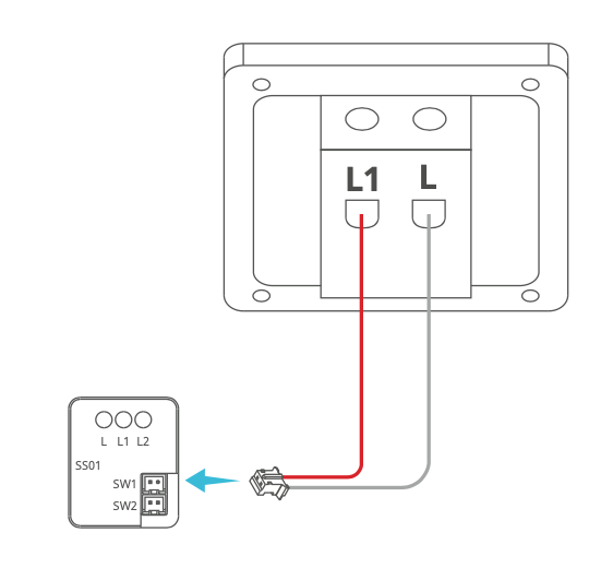
The In-Wall Relay Switch consists of two parts, the Smart Relay and the optional Smart Switch Sub-Assembly. One Smart Relay can be connected to one or a series of Smart Switch Sub-Assemblies (Multiple-point control). One Smart Switch Sub-Assembly can be connected to two circuits of loads, each of which must use one Smart Relay.
This document illustrates the connection of the Smart Switch Sub-Assembly to different switches. It also provides six wiring examples of the In-Wall Relay Switch:
- 1-gang switch controlling one light
- 1-gang switch controlling a group of lights
- 2-gang switch controlling two lights
- 3-way control of one light
- Multi-way control of one light
- Double 3-way control of two lights
- Double multi-way control of lights
- Connecting to Different Switches
- Wiring Examples
Connecting to Different Switches
1-gang switch
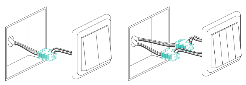
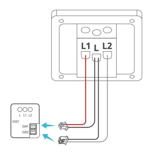
2-gang switch
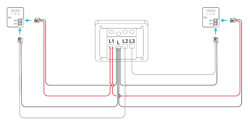
3-gang switch
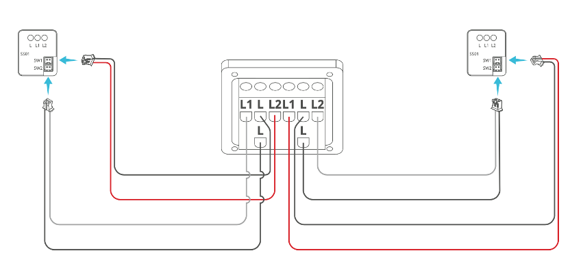
4-gang switch
More switches
Wiring Examples
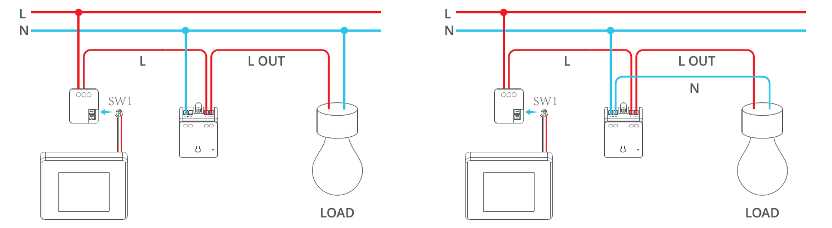
Example 1: 1-gang switch that controls one light
Prepare 1 Smart Switch Sub-Assembly and 1 Smart Relay
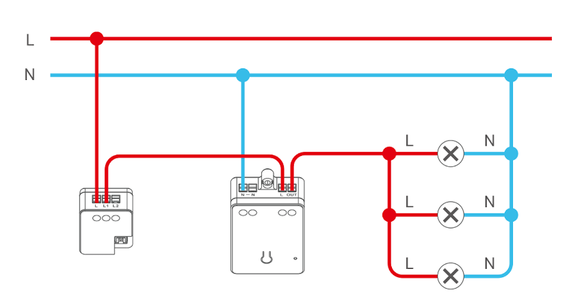
Example 2: 1-gang switch that controls a group of lights
1) All lights are connected to 1 Smart Relay
In this way, you can control all the lights at the same time with the wall switch and the App.
Prepare 1 Smart Switch Sub-Assembly and 1 Smart Relay.
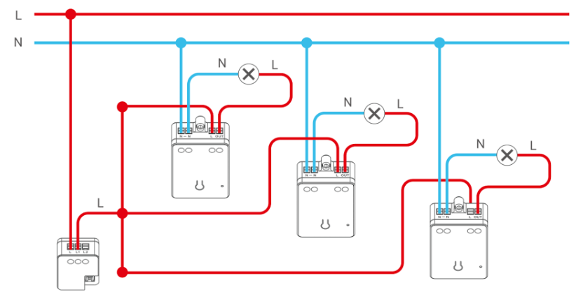
2) Each light is connected to one Smart Relay separately
In this way, you can use the wall switch to control all the lights at the same time and use the App to control each light individually and/or at the same time.
Prepare 1 Smart Switch Sub-Assembly and Multiple Smart Relays.
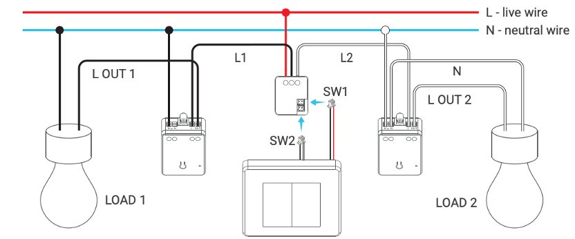
Example 3: 2-gang switch that controls two lights independently
Wiring steps:
Prepare 1 Smart Switch Sub-Assembly and 2 Smart Relay
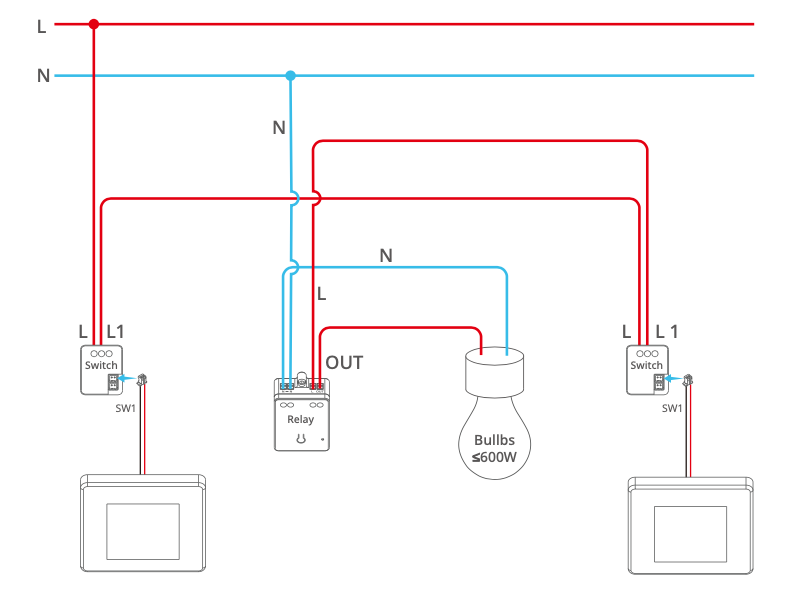
Example 4: 3-way control of one light fixture
3-way control refers to two switches in different places that can control one light at the same time. This type of wiring can be found, for example, in bedrooms where there are switches both at the entrance and at the bedside to control the lights, and in staircases where there are switches both downstairs and upstairs to control the lights.
Wiring steps:
- Prepare 2 Smart Switch Sub-Assembly and 1 Smart Relay
- According to the wiring diagram, install the 2 Smart Switch Sub-Assemblies in the two switch boxes respectively, and install the Smart Relay to the lamp. (Note: Only one of the two traveler wires is used)
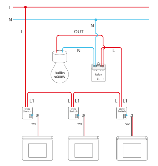
Example 5: multi-way control of one light fixture
Multi-way control refers to three or more switches in different places that can control one light at the same time.
Wiring steps:
- Prepare multiple Smart Switch Sub-Assemblies (one for each switch) and 1 Smart Relay
- According to the wiring diagram, install the Smart Switch Sub-Assembly in each of the switch boxes and install the Smart Relay at the light fixture. (Note: Only one of the traveler wires is used)
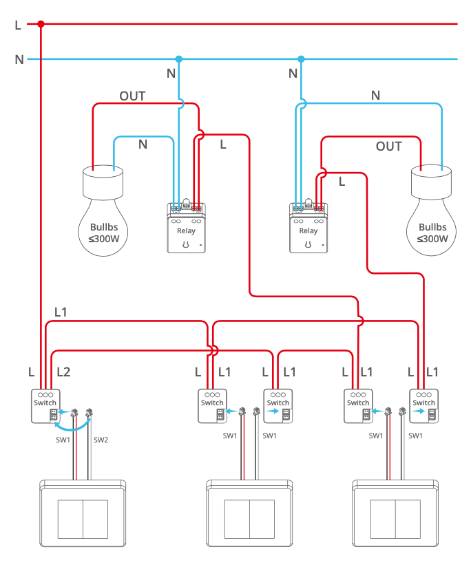
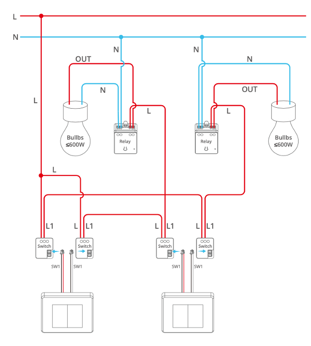
Example 6: double 3-way control of two light fixtures
Double 3-way control refers to two 2-gang switches in different places, each of which can control one light respectively.
Wiring steps:
- Prepare 3 or 4 Smart Switch Sub-Assembly and 2 Smart Relays.
- According to the wiring diagram, install the Smart Switch Sub-Assemblies in each of the switch boxes and the Smart Relays to the respective light fixtures. (Note: Only one of the traveler wires is used for each 3-way control, and the second switch box needs to be installed with two Smart Switch Sub-Assembly).
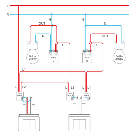
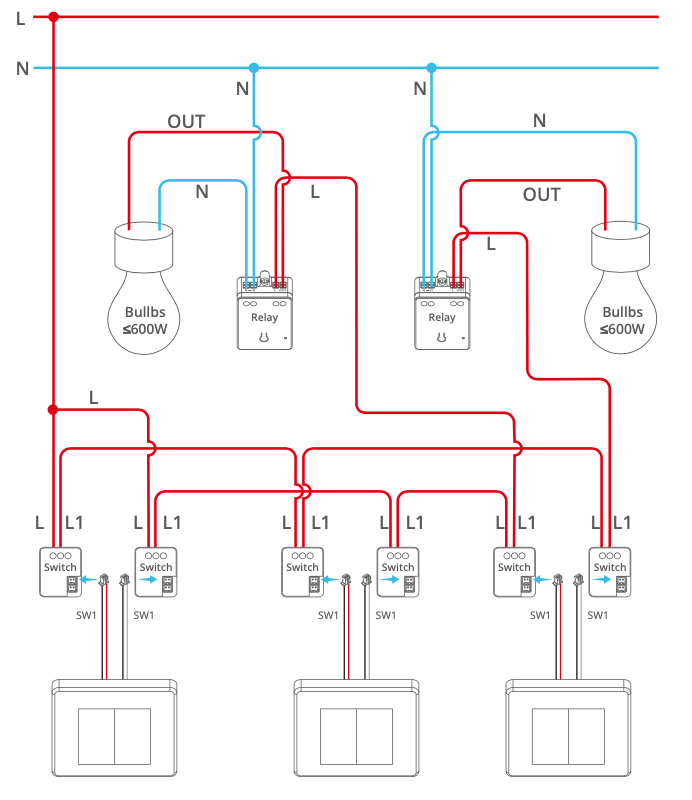
Example 7: double multi-way control
Double multi-way control refers to multiple 2-gang switches in different places, each of which can control one light respectively.
Wiring steps:
- Prepare multiple Smart Switch Sub-Assemblies and 1 Smart Relay according to the wiring diagram
- Install the Smart Switch Sub-Assemblies in each of the switch boxes and the Smart Relay at the lamp. (Note: Only one of the traveler wires is used for each 3-way control; the second and later switch boxes need to be installed with two Smart Switch Sub-Assemblies)